With the increasing popularity of high-power cutting heads, we have found that there are more and more cases of protective lens bursting. The reason is mostly caused by pollution on the lens. When the power is increased to more than 10,000 watts, once dust pollution occurs on the lens, and the burning point is not stopped in time, the energy absorbed instantly increases, and it is easy to burst. The lens burst will cause a greater failure problem to the cutting head. So today we will talk about measures that can effectively prevent the protective lens from bursting.
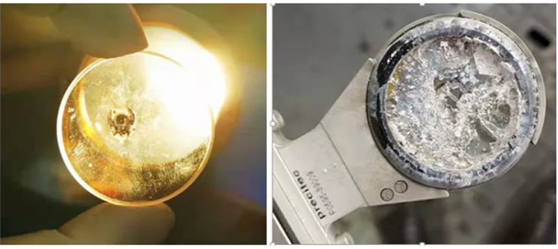
Protect the burned spots and cracked lenses on the mirror
Cutting gas
About pipeline inspection:
The gas path inspection is divided into two parts, one is from the gas tank to the gas outlet of the gas pipe, and the other is from the gas outlet of the gas pipe to the cutting gas connection port of the cutting head.
Checkpoint 1 .Cover the tracheal outlet with a clean white cloth, ventilate for 5-10 minutes, check the condition of the white cloth, use a clean protective lens or glass, place it at the tracheal outlet, ventilate at low pressure (5-6 bar) for 5-10 minutes, and check whether the protective lens is There are water and oil.
Checkpoint 2 .Cover the tracheal outlet with a clean white cloth, ventilate for 5-10 minutes, check the condition of the white cloth, use a clean protective lens or glass, place it at the tracheal outlet, and ventilate at low pressure (5-6 bar) for 5-10 minutes (exhaust 20s; stop) 10s), check whether there is water and oil in the protective lens; whether there is air hammer.
Note: All tracheal connection ports should use card sleeve pipe joints as much as possible, do not use quick-connect ports as much as possible, and avoid using 90° ports as much as possible. Try to avoid the use of raw material tape or thread glue, so as not to cause the raw material tape to break or thread glue debris into the air path, causing air path pollution to block the proportional valve or cutting head, resulting in unstable cutting or even cutting head lens burst. It is recommended that customers install a high-pressure and high-precision (1μm) filter at check point 1.
Pneumatic test: do not emit light, run the entire perforation and cutting process in an empty run, and whether the protective mirror is clean.
B.Gas requirements:
Cutting gas purity:
| Gas | Purity |
| Oxygen | 99.95% |
| Nitrogen | 99.999% |
| Compressed air | No oil and no water |
Note:
Cutting gas, only clean and dry cutting gas is allowed. The maximum pressure of the laser head is 25 bar (2.5 MPa). Gas quality meets ISO 8573-1:2010 requirements; solid particles-class 2, water-class 4, oil-class 3
| Grade | Solid particles (remaining dust) | Water(Pressure dew point)
(℃) |
Oil (Steam/Fog)
(mg/m3) |
|
| Maximum density (mg/m3) | Maximum size (μm) | |||
|
1 |
0.1 |
0.1 |
-70 |
0.01 |
|
2 |
1 |
1 |
-40 |
0.1 |
|
3 |
5 |
5 |
-20 |
1 |
|
4 |
8 |
15 |
+3 |
5 |
|
5 |
10 |
40 |
+7 |
25 |
|
6 |
– |
– |
+10 |
– |
C.Cutting gas input pipeline requirements:
Pre-blowing: before perforation (about 2s), the air is discharged in advance, and the proportional valve is connected or the feedback of the 6th pin of the IO board is connected. After the PLC monitors that the cutting air pressure reaches the set value, the light emission and perforation process will be carried out. Keep blowing. After the piercing is finished, the air will continue to vent and descend to the cutting follow-up position. During this process, the air will not stop. The customer can switch the air pressure from the piercing air pressure to the cutting air pressure. Switch to the perforation air pressure during the idle movement, and keep the gas off, move to the next perforation point; after the cutting is completed, the gas will not stop and lift up, and the gas will stop after being in place with a delay of 2-3s.
Alarm signal connection
A.PLC alarm connection
During equipment commissioning, it is necessary to check whether the alarm signal connection is correct
- The PLC interface first checks the alarm priority (second only to emergency stop) and the follow-up action settings after the alarm (light stop, stop action).
- No light inspection: pull out the lower protective mirror drawer a little bit, LED4 alarm appears, whether the PLC has alarm input and subsequent actions, whether the laser will cut off the LaserON signal or lower the high voltage to stop the laser.
- Light-emitting inspection: Unplug the 9th pin alarm signal of the green IO board, and whether the PLC has alarm information, check whether the laser will drop high voltage and stop light-emitting.
If the OEM has received the alarm signal, the priority is second only to the emergency stop (fast transmission channel), the PLC signal responds quickly, and the light can be stopped in time, and other reasons can be checked. Some customers use the Baichu system and have not received the alarm signal. The alarm interface needs to be customized and set the follow-up action (stop light, stop action).
For example:
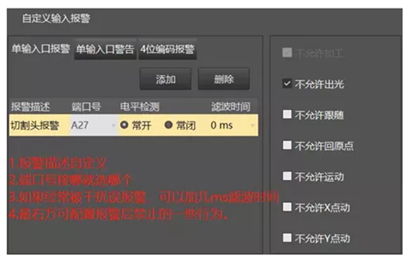
Cypcut system alarm settings
B.Optocoupler electrical connection
If the PLC does not use the fast transmission channel, there is another possibility that the laser can be turned off in a short time. The cutting head alarm signal is directly connected to the optocoupler relay to control the LaserON signal (theoretically, the laser safety interlock can also be controlled), and the light is directly cut off (the laser enable is also set to low -> laser off). However, it is necessary to connect the alarm signal Pin9 to the PLC in parallel, otherwise the cutting head alarms, and the customer does not know why, but the laser suddenly stops.
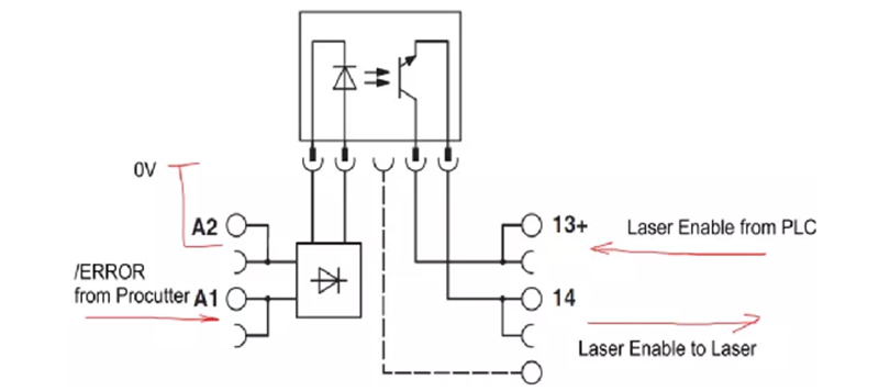
Connection of opto-coupled electrical appliances (alarm signal-opto-coupled electrical appliances-laser)
As for the temperature gradient, this needs to be tested and set by the OEM according to the actual cutting situation. The 6th pin of the IO board defaults to output the monitoring value of the protective mirror temperature (0-20mA), and the corresponding temperature is 0-100 degrees. If the OEM wants to do it, it can do it.
Use original protective lenses
The use of non-original protective lenses can cause many problems, especially in the 10,000-watt cutting head.
1.Poor lens coating or poor material can easily cause the temperature of the lens to rise too fast or the nozzle to become hot, and the cutting is unstable. In severe cases, the lens may explode;
2.Insufficient thickness or error in the edge size will cause air leakage (air pressure alarm in the cavity), contaminate the protective lens in the focusing module, resulting in unstable cutting, impenetrable cutting, and serious pollution of the focusing lens;
3.The cleanliness of the new lens is not enough, causing frequent burnout of the lens, pollution of the protective lens in the focusing module, and serious lens explosion.
Post time: Aug-25-2021